Power Hat for Computing Module in Bipedal Robot
Power Supply, Protection, and Monitoring Hat for Robot Onboard SBC
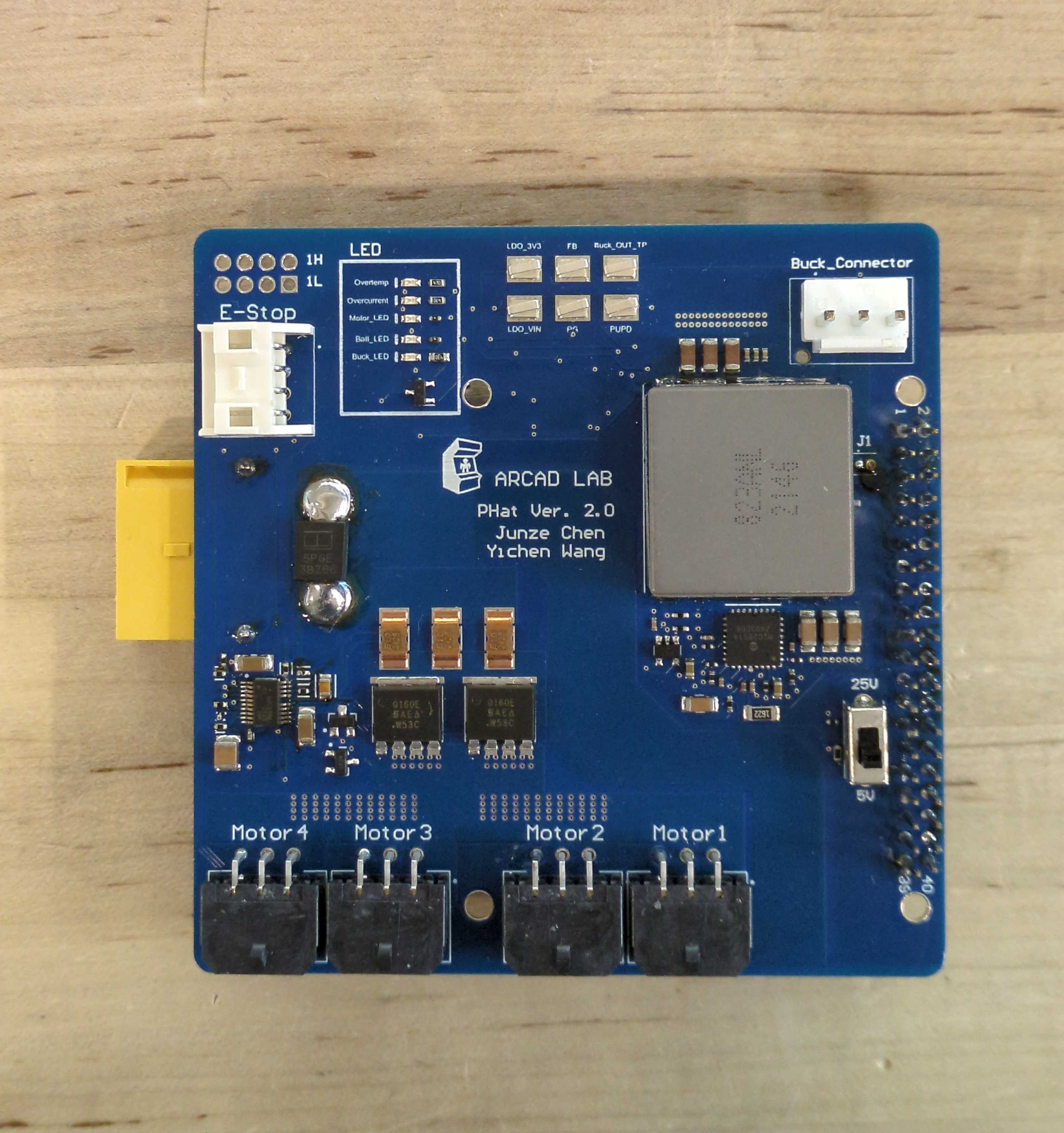
When we first developed the hopper (MUPS), we just connected the motors directly to the battery with a wire. That worked, but we found it hard to track the power consumption of the robot, and it felt very sketchy. We were afraid we would crash the robot, short a wire, and catch something on fire. Its also good practice to have a way of arresting the surge current when we connect a large capacitive load. So we designed the Power Hat to put all the power electronics in one spot!
On the project was me, and Junze, our resident electrical engineering undergrad. I designed the majority of the schematic and circuit, and Junze did most of the legwork in layout and ordering. I also helped route some important power pours and some parts that need special treatment.
Our first version of the board was riddled with issues. We thought we'd throw in a buck converter to power the Raspberry Pi, but we undersized the inductor and it could not supply enough current. I also spec'ed a 4kΩ resistor as a 4Ω resistor, which caused a lot of problems. We actually designed an intermediate board to iron out the kinks of the buck converter before moving on to the full v2.
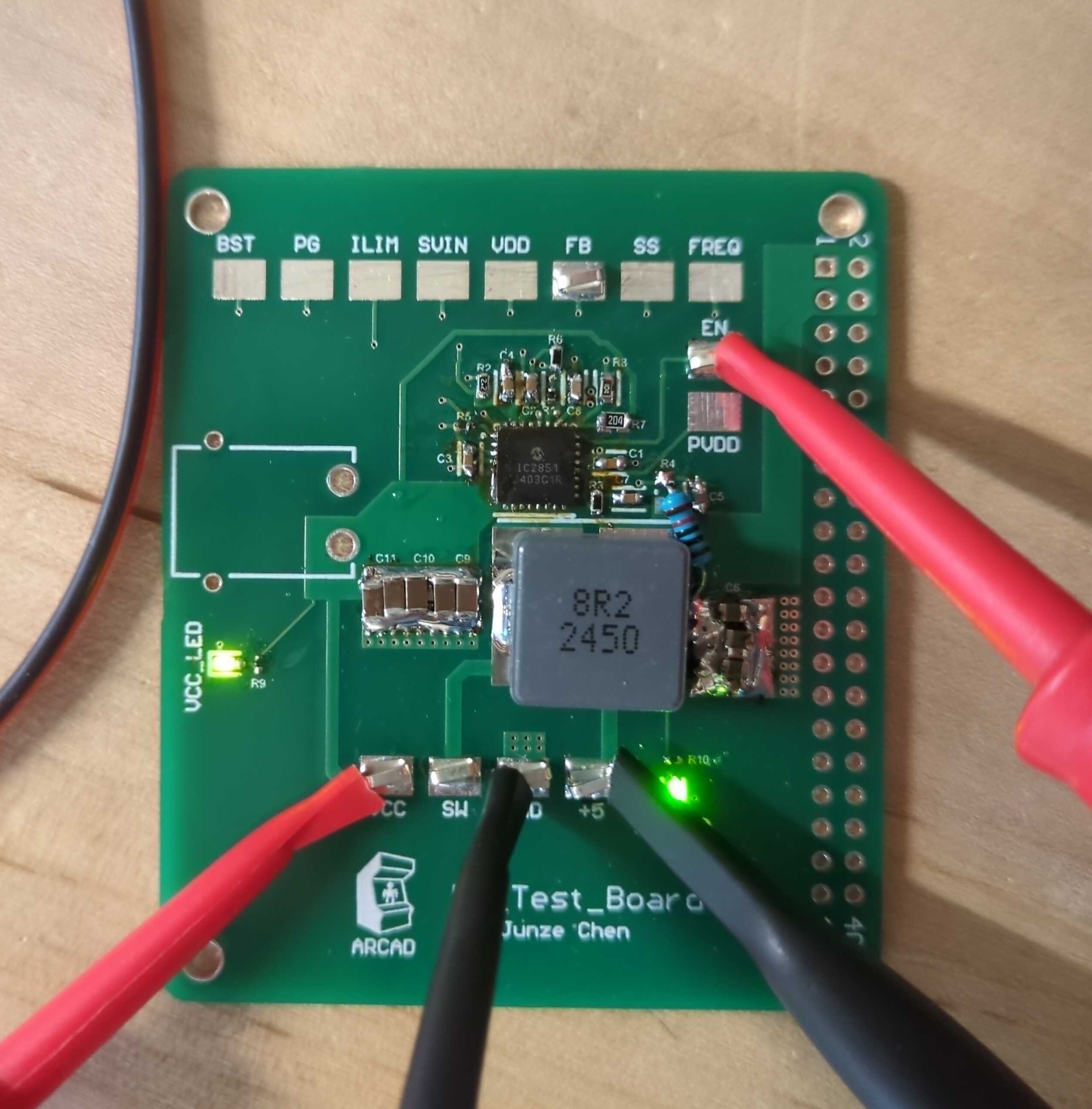
You can tell it's a test board by the bodge-resistor and half-populated testpoints. I was the only person capable of soldering 0402 resistors, so I got my year's worth of lead fumes assembling that board. After we were confident we can nail the buck converter, we designed a v2 for the power hat. We slipped in some extra features, including a switchable voltage buck converter, with a max output of more than 100W.
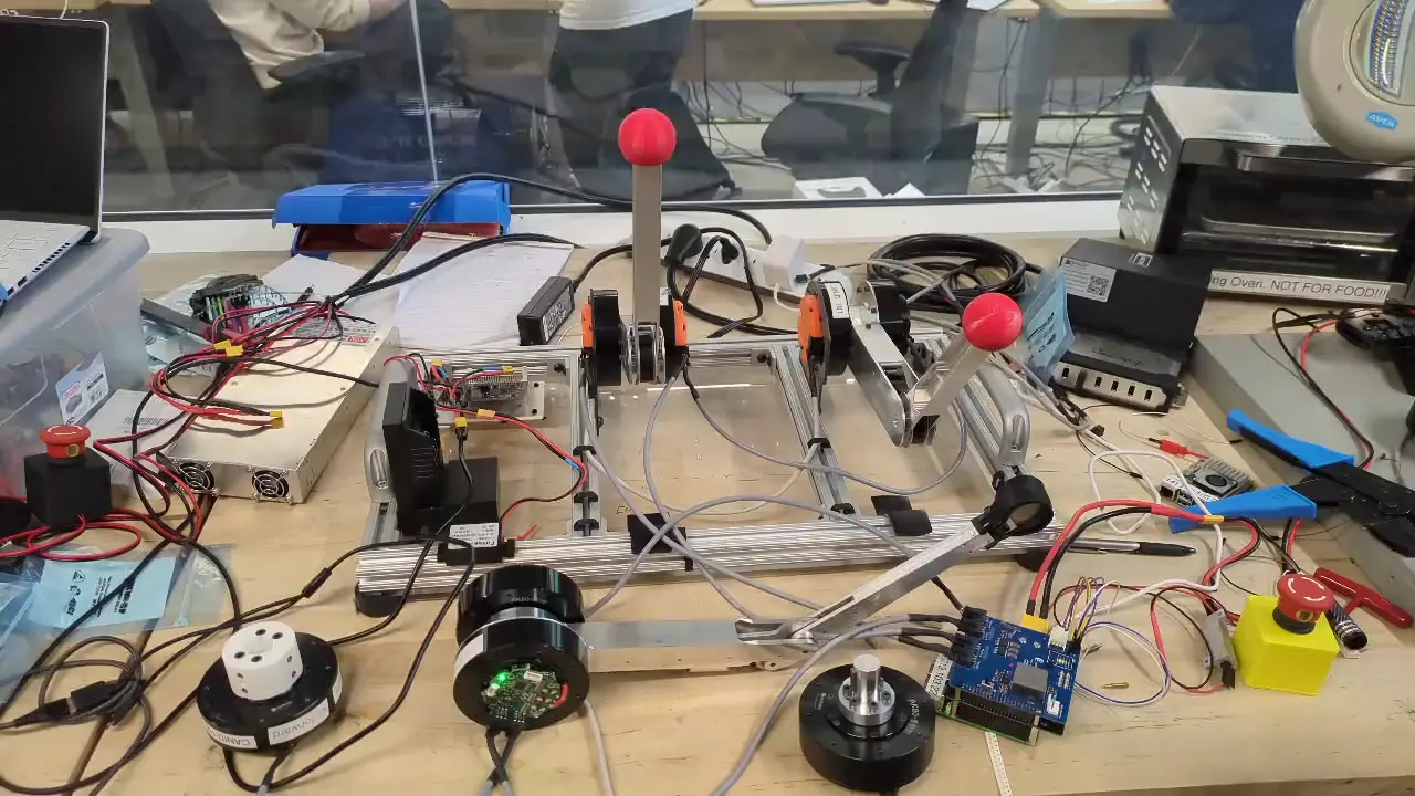
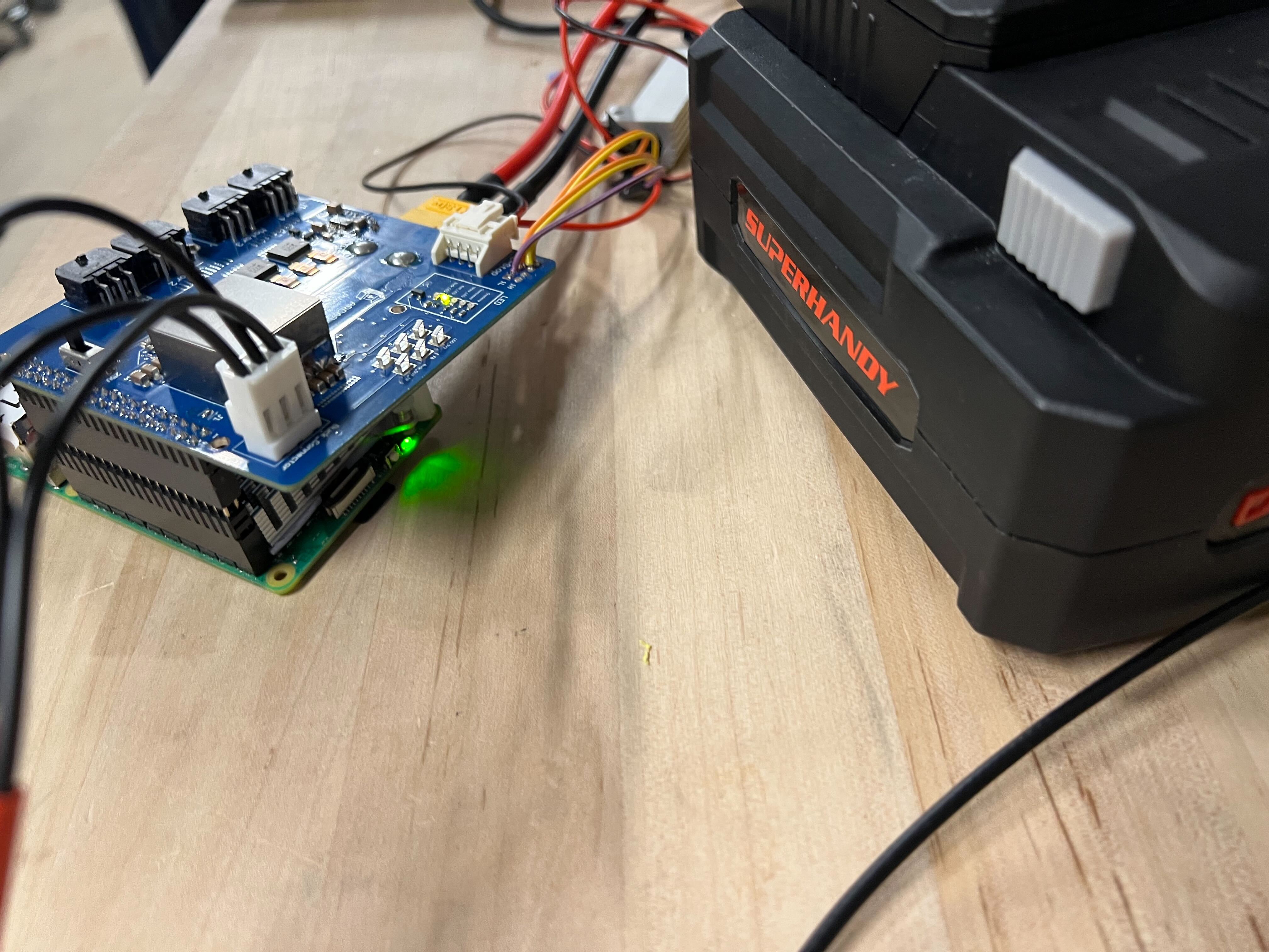
Here is the power hat supplying power to eight motors simultaneously in a stress test using our teleoperation demo rig. Its power monitoring capability has already been super useful around the lab.
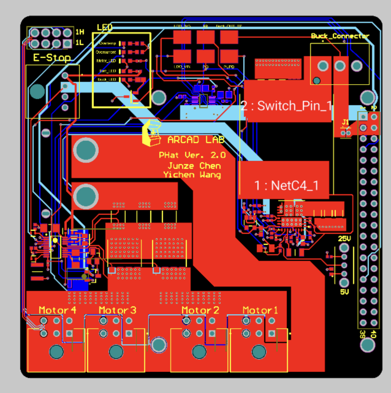
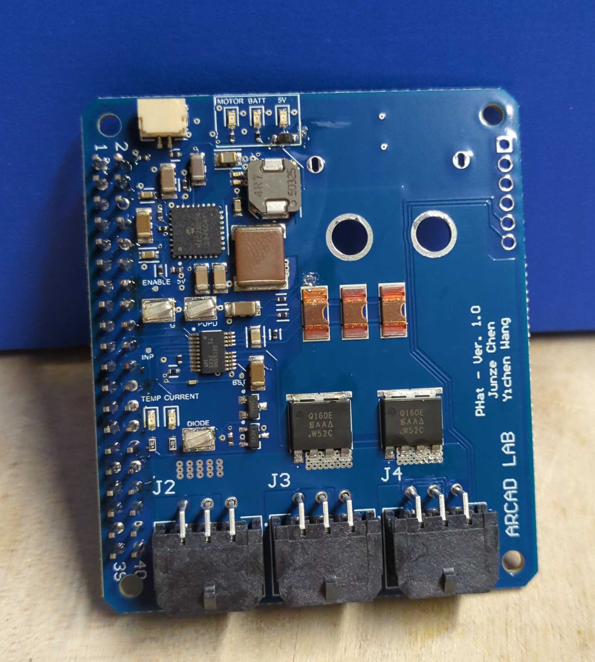
This is the overall schematic of the power hat, minus the ground plane. The beefy power pours on the bottom left Are actually copied on all four layers to provide enough current capacity without overheating the board. I became very afraid of batteries after the testing of this board, because for a brief week it would explode every time we connected it to a battery.
Turns out, it was because a smoothing resistor caused the voltage on the supply pin to fall under that of a current sending pin during the power-on transient. It was easily fixed by just removing the resistor, but it did strike fear into my heart. Even though I designed it, it still feels like a miracle that it actually works.